Monday 30 January 2017

Functional mechanical design ( Results)

Hi,
Navindran S/O Chandran/ Navindran Chandran
Diploma in Mechnical Engineering @Singapore Polytechnic
Works as Fablab Assistant @ Fablab @Singapore Polytechinc

Hi guys,as I said in the last post yesterday, I try out the experiment and I have a good results

Shout out to Tze Chuan for the comment it was really helpful.

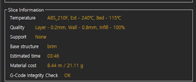
Now I will be discussing about my cubicon setting:


This is the setting I put for the mounting that I did.


This will be the time taken to print and details about the layers and tolerance


The execution of the experiment

I did this in one try and it works gladly

The picture below will be the time I slot in the M8 nut


The slotting in the M8 nut need some gut feeling and some calculation as one layer is 0.2mm you will roughly know when to slot the nut in . Please make sure that you guys take in the consideration  of the nozzle head as the nut may effect the printing .  Believe it or not I was sitting infront of  my 3D printer for 45 minutes from the time my hexagon start forming just to get the confidence to slot in my M8 nut .Phew... Any way it's done and I'm happy to see the final product.

The Final product:


Sorry if you guys can't see the M8 nut as my lab here have poor lighting and my smartphone camera is not that good.


This is the video with mmy lead screw to see whether it's working or not

It works fine for now let see when I add my other parts.

As ABS have a mechanical properties :


I think this experiment that I have succeed will work for a long time

Thanks,


Regards,
Navin


Sunday 29 January 2017

Functional mechanical design

Hi,
Navindran S/O Chandran/ Navindran Chandran
Diploma in Mechnical Engineering @Singapore Polytechnic
Works as Fablab Assistant @ Fablab @Singapore Polytechinc

Sorry for a quite a log break for my blog as I was busy with my studies and project you guys can follow my project here:

My current project link

I had a chance to take a project in my school where I will be implementing my idea in Indonesia . Please take a look as it may give us a solution in singapore for urban farming to find out more please click on the link above.

I'm writing a post today, to document my experiment that I gonna conduct for my project, I have a lead screw to do an actuator that I'm gonna use it for my project above. I can't find lead nut with mounting and it's quite expensive and will take a long time to get in my hand.

The information about the lead screw:

M8 Lead screw 50cm long

I will be using cubicon as I want it to be fast and reliable. The material filament is ABS

So what I'm gonna do is I'm gonna design a mounting lead nut by putting my nut during the printing it self. That's why I said that this is a experiment to find whether when I add foreign material can I get a rigid structure

This will be the design where the dotted line is my slot for my M8 nut

And I gonna add my M8 screw when my printing  reach here.


You guys may ask why not you print M8 thread using Cubicon . It will a long time to print and the resolution of printer is not good that M8 thread will be not M8. By doing this I think that I may reduce some time. Tommorrow , I will be executing my design and will do a post later.
So for now I think this post will give you the idea

Wednesday 14 September 2016

Chain Pump - Module Project

Chain Pump


Navindran S/O Chandran/ Navindran Chandran
Diploma in Mechnical Engineering @Singapore Polytechnic
Works as Fablab Assistant @ Fablab @Singapore Polytechinc

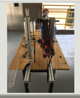
This is my module project and I don't know what grade I get. The module called Engineering Invention from Engineering Academy. Basically this project is about Ancient Invention the theme I get is South- East Asia Ancient Invention. I had a group of consist of 3 DEEE( Dip.Electrical & Electronic Engineering) student and 2 DME(Dip.Mechanical Engineering) student. So we were told select 3 Asian Ancient Invention. So we select Water-clock , Chain pump and Water - Hammer. Then my lecturer in- charge ask us to do Chain pump..

So what I had in my mind was last time I did a project where I have a rusty attachment chain that I buy to make a threaded wheel. So I use that. So we had 2 prototype presentation

So this will be the first one;
From the left; The overall prototype, electronic component , and the support system..


Challenges:
Problem that we face was the attachment chain and the sprocket doesn't fit as we were using Bicycle sprocket and K-35 attachment chains.
Our prototype was a kind of big and take to much space
No Mobility. Cannot move around with that.

Improvement that targeted to do:
Use only one stand and make it retractable
Decrease the chain size by half
Find a suitable Sprocket.
Do a stopper that we can only rotate it in one direction.

Second and Final Prototype:

The Second prototype was a success but there was no good finishing as the rusting of the chain becoming worse but the prototype works.


What I did??

I use a 8mm acrylic as a working support where we attached the acrylic to connect the driven and effort shaft together firmly and it's works.

Not only that I found the file for K-35 sprocket online:

I just laser cut using acrylic .
I tried to 2d router using aluminium but it doesn't turn out well. So we stick with acrylic.

Breaking the chain is the hardest thing that I do in this project .
But I manage too break it.

Below will be the CAD drawing report that maybe will give you the understanding.

For more brief pictures I will send put the pdf file.


Materials that I use for this project:
  1. Aluminium Extrusion 40 x 40 L500mm&L400mm(Support system)
  2. Acrylic 3mm 8mm( For sprocket, hooks, one way gear mechanism, box for electronic parts and the working support)
  3. Steel pipe D6mm L200mm
  4. PVC pipe D10mm L500mm ( we use it for the lever with 90degree connector)
  5. M4 screw multiple lengths
  6. Wood for the retractable usages
  7. K35 attachment chain.
  8. Tin cans
  9. ABS for 3d printing purpose
  10. LCD screen
  11. Ultrasound sensor 2
  12. Bluetooth receiver..
  13. Adjusting switch
  14. Arduino kit
  15. Connecting Wire.
Fabrication Techniques
  1. 3D-  printing
  2. Laser cutter
  3. 2D- router
  4. Vertical Miling
Target that I achieve:
Make it portable (ACHIEVED)
Make it smaller then first project(ACHIEVED)
Make a stopper ( ACHIEVED)
Find a suitable sprocket(ACHIEVED

Video:


Thursday 23 June 2016

Party Cannon

The Party Cannon - MakerFaire

Navindran S/O Chandran/ Navindran Chandran
Diploma in Mechnical Engineering @Singapore Polytechnic
Works as Fablab Assistant @ Fablab @Singapore Polytechinc
The Cannon

Material:
1. 80mm diameter Pipes (about 10cm long)

2. 80mm diameter pipes(End Cap) 


3. 80mm - 50mm reducer connector

4. 50mm diameter pipe (8cm)

5. 50mm diameter threaded connector. (2 pieces)
6. Ball valve (50mm)
7. 50mm diameter pipe (10cm)
8. Tank Valve (Male) (You can get this from a motorbike shop)
9. Others
    •Pipe glue
    •Blue cement (PVC glue is good enough)
    •Gap sealer
    •Confetti
    •Balloon
    •Candy
    •Air pump

Plan:


Detailed plan:

Note:
 The tank valve is connected at the 80mm end cap by drilling a hole on it. The tank valve (male) that you buy may vary so  drilling the hole may not applicable for this.


Steps:
I followed all the steps from this link

Cannon first edition


Flaws:

The Ball Valve was very hard to turn.
There are some air leakages.


Second edition Canon:

Modification:

First flaw: The ball valve was very tight and it couldn't be turned.

How do solve the flaws:
We used the fulcrum theory to fix the problem

Material:

1. A wooden piece (I took it from fablab recycle corner)


2. Hinges (Also took it from fablab recycle corner)


Plan:


Second flaw: It's has air leakages.

How I solved the problem.
I used a gap sealer to solve the problem . There were some conventional gap sealer available at a hardware shop.

Cannon edition 2:

Some videos;


My party cannon was a little plain, and my lecturer(Mr.Teo Shin Jin) suggested that I decorated it to make it look more like a cannon for a party. The balloon is not meant for decoration, but to work as a diaphragm; such that the air contained in the balloon will act as a  sling to the payload


Sorry I couldn't be there, I'm in Japan for student's exchange programmes.
Will meet you guys other time with more inventions and makings...


•